Cythonizing your Python code, Part 1: the basics.

Intro to Python and Cython

Python has become one of the most loved and in demand programming languages in fields from data science and artificial intelligence to web and app development. Compared to lower-level programming languages like C/C++, Python puts an emphasis on readability and simplicity (you will often read that “Pythonic” code should be “beautiful”). This helps to accelerate the pace of program development and improve the sharing of ideas. According to Python developer Guido van Rossum,

Typically when you ask a programmer to explain to a lay person what a programming language is, they will say that it is how you tell a computer what to do… In reality, programming languages are how programmers express and communicate ideas — and the audience for those ideas is other programmers, not computers. The reason: the computer can take care of itself, but programmers are always working with other programmers, and poorly communicated ideas can cause expensive flops.

What we commonly call Python is really two different things: the language and the implementation. The Python language defines the syntax with which we write code. The most common implementation is CPython (written in C and Python), which compiles valid Python code into bytecode and then interprets it in real time as the program runs.

One of the reason’s for Python’s popularity is the flexibility afforded by its dynamic typing and memory management. I can define a variable x = 5, divide x by 2 to get 2.5, and then later set x = 'Florida'. In this sequence, x will have been typed as an integer, a float, and then a string. Python can do this for us automatically with no problem; under the hood it is dynamically allocating/deallocating memory, checking for type compatibility with mathematical operations, etc.

However, this flexibility has a cost, as it requires the interpreter to run a large number of tasks and checks behind the scenes at run time. Lower-level compiled languages like C require the user to pre-specify the type for each variable, how to allocate and deallocate memory, etc. This structure makes them less flexible and more difficult to use, but potentially much faster. In many applications Python is significantly slower (e.g., 10-100x) than typed, compiled languages such as C/C++.

Cython is an attempt to bridge the gap by bringing some of C’s qualities to Python. It is technically a separate programming language which is a superset of the Python language; Cython code mostly looks like Python code, but it also adds optional C-inspired syntax. Most notably, it allows us to declare static types when defining variables/classes/functions.

Cython can automatically translate our code into C, which can then be then compiled into CPython extension modules. These compiled modules can be imported and used within Python code with significantly lower overhead than the equivalent Python modules.

Software

You can find all code used in this blog post at this GitHub repository.

If you want to follow along and build Cython code on your own machine, you will need a working Python 3 environment (preferably 3.6+ to avoid dependency issues) with NumPy, Cython, Matplotlib, and Jupyter.

You will also need the right compiler. OSX and Linux (including WSL) users should already have gcc standard. Windows users who don’t use WSL will need to download Microsoft Visual Studio 2019 to make sure you have the right compiler. Choose “Desktop development with C++” when it asks which programs you want to install.

A simple example: the Fibonacci sequence

The Fibonacci sequence is defined through the following recurrence relation:

Fn = Fn-1 + Fn-2

The sequence begins 0, 1, 1, 2, 3, 5, 8, …

In this blogpost we will build several versions of a function to calculate the n’th Fibonacci number. All scripts associated with this example can be found in the “fibonacci/” directory of the repository above. The examples in this section are adapted from Kurt W. Smith’s O’Reilly Media book, “Cython: A Guide for Python Programmers“.

First, consider the pure Python implementation of this function, saved as fib_py.py:

def fib_py(n):
    a, b = 0, 1
    for i in range(n - 1):
        a, b = a + b, a
    return a

We can import and run this function, and print the 30th Fibonacci number as follows:

from fib_py import fib_py
print(fib_py(30))

The output is 514229, which is indeed the 30th number in the sequence.

The second file in the repository, fib_py_cy.py, is identical to the first script. We will “Cythonize” it to compiled C code without making any manual changes.

The third version, fib_cy.pyx, is a Cythonic implementation. Note the new file ending, .pyx, for Cython source files. Each variable is now statically typed as an integer. In the function body, this is done by prefacing the variable definition by cdef. The cdef is not necessary for arguments in the function definition (e.g., n).

def fib_cy(int n):
    cdef int a = 0
    cdef int b = 1
    cdef int i
    for i in range(n - 1):
        a, b = a + b, a
    return a

Because of the importance of types for Cython, I have also included three more files which are equivalent to the first three, except that they use floating point numbers to count rather than integers. Note that, confusingly, the Python float class is equivalent to C doubles, not C floats.

Here is fib_py_double.py and fib_py_cy_double.py. These don’t explicitly define a static type, but a and b are defined using a decimal so that they will be stored as floating points rather than integers (e.g., 0. rather than 0).

def fib_py_double(n):
    a, b = 0., 1.
    for i in range(n - 1):
        a, b = a + b, a
    return a

And here is fib_cy_double.pyx with statically defined types:

def fib_cy_double(int n):
    cdef double a = 0.
    cdef double b = 1.
    cdef int i
    for i in range(n - 1):
        a, b = a + b, a
    return a

In order to run the Cython code, we first have to Cythonize it. This involves two steps: translating our Python-like code into C code, and compiling the C code into an executable. If you want to repeat this process on your own machine, first delete all *.so, *.pyd, *.c, and *.html files, as well as the build/ directory.

To Cythonize, we use a setup file, setup_fibs.py:

from setuptools import setup
from Cython.Build import cythonize

setup(ext_modules = cythonize(['fib_py_cy.py', 'fib_cy.pyx', 'fib_py_cy_double.py', 'fib_cy_double.pyx'], annotate=True, language_level=3))

and run it in Python:

python3 setup_fibs.py build_ext --inplace

We get the following output:

Compiling fib_py_cy.py because it changed.
Compiling fib_cy.pyx because it changed.
Compiling fib_py_cy_double.py because it changed.
Compiling fib_cy_double.pyx because it changed.
[1/4] Cythonizing fib_cy.pyx
[2/4] Cythonizing fib_cy_double.pyx
[3/4] Cythonizing fib_py_cy.py
[4/4] Cythonizing fib_py_cy_double.py
running build_ext
building 'fib_py_cy' extension
creating build
creating build/temp.linux-x86_64-3.8
x86_64-linux-gnu-gcc -pthread -Wno-unused-result -Wsign-compare -DNDEBUG -g -fwrapv -O2 -Wall -g -fstack-protector-strong -Wformat -Werror=format-security -g -fwrapv -O2 -g -fstack-protector-strong -Wformat -Werror=format-security -Wdate-time -D_FORTIFY_SOURCE=2 -fPIC -I/usr/include/python3.8 -c fib_py_cy.c -o build/temp.linux-x86_64-3.8/fib_py_cy.o
creating build/lib.linux-x86_64-3.8
x86_64-linux-gnu-gcc -pthread -shared -Wl,-O1 -Wl,-Bsymbolic-functions -Wl,-Bsymbolic-functions -Wl,-z,relro -g -fwrapv -O2 -Wl,-Bsymbolic-functions -Wl,-z,relro -g -fwrapv -O2 -g -fstack-protector-strong -Wformat -Werror=format-security -Wdate-time -D_FORTIFY_SOURCE=2 build/temp.linux-x86_64-3.8/fib_py_cy.o -o build/lib.linux-x86_64-3.8/fib_py_cy.cpython-38-x86_64-linux-gnu.so

...

copying build/lib.linux-x86_64-3.8/fib_py_cy.cpython-38-x86_64-linux-gnu.so ->
copying build/lib.linux-x86_64-3.8/fib_cy.cpython-38-x86_64-linux-gnu.so ->
copying build/lib.linux-x86_64-3.8/fib_py_cy_double.cpython-38-x86_64-linux-gnu.so ->
copying build/lib.linux-x86_64-3.8/fib_cy_double.cpython-38-x86_64-linux-gnu.so ->

This output has several steps. First, Python checks which of our files has changed since the last Cythonization (in this case, all of them, since we deleted all previous Cython files). Each of these is Cythonized, creating a *.c file. Then each *.c file is compiled using gcc to create a *.so dynamic library, which is able to communicate directly with CPython at runtime (this may be a *.pyd file if you are using Windows without WSL). Finally, the files are copied from the build/ directory to the working directory, where they can be imported by Python scripts.

If you look at the C files, you will notice they are much longer and more complicated than the original Python file, or for that matter, than a true C implementation would be. For example, my version of fib_cy.c is 3179 lines long. The vast majority of this is specialized functions for interfacing between C and Python and handling various errors and exceptions. Thankfully, when programming in Cython we generally don’t have any need to edit or interpret the C files themselves.

Also created is a *.html annotation file that can be opened in the browser. These files highlight regions of the original Cython file based on how much Python interaction they require at runtime. For example, compare the highlighting for fib_py_cy.py and fib_cy.pyx:

Cython annotation for fib_py_cy.py
Cython annotation for fib_cy.pyx

The former, which does not include static type information, has significant interaction with the Python interpreter due to the need for dynamic type checking and memory management throughout the loop. The latter, on the other hand, only interacts with Python when calling and returning from the function; the internal computation of the loop is self-contained C code. If you click on particular highlighted lines, you can expand to see the specific C code associated with those lines.

So how do the performance of these different versions compare? The time_versions.py script will run 10×100,000 repetitions of each version of our code, given a Fibonacci sequence number (e.g., 30) that is supplied as a command line argument:

$ python3 time_versions.py 30

Pure python: answer = 514229, time = 0.07640906400047243, speedup = 1.0

Cythonized Python: answer = 514229, time = 0.03642013104399666, speedup = 2.0979898152526655

Typed Cython: answer = 514229, time = 0.0032417900511063635, speedup = 23.570022362921193

Pure Python (double): answer = 514229.0, time = 0.06389092199970037, speedup = 1.1959299006646167

Cythonized Python (double): answer = 514229.0, time = 0.016547597013413906, speedup = 4.617532318350108

Typed Cython (double): answer = 514229.0, time = 0.002909799979534, speedup = 26.259215251183424

For each of our six version, the answer calculated is the same, as expected. The “speedup” is calculated as the runtime for the pure Python integer implementation, divided by the runtime for the implementation of interest. The speedup is found to be 2.1 for fib_py_cy.py, the version that was Cythonized without explicitly adding type information. Pretty good for basically no work! However, the speedup for the statically typed version is much larger, at 23.6. This highlights how important dynamic type checking and memory management are as a bottleneck for Python. The double versions are found to be somewhat faster than the integer versions as well.

However, redoing the analysis for n=50 highlights an important lesson:

$ python3 time_versions.py 50

Pure python: answer = 7778742049, time = 0.1132775130099617, speedup = 1.0

Cythonized Python: answer = 7778742049, time = 0.06092342402553186, speedup = 1.8593425241905186

Typed Cython: answer = -811192543, time = 0.003898979048244655, speedup = 29.053121755286153

Pure Python (double): answer = 7778742049.0, time = 0.09670376998838037, speedup = 1.1713867310816608

Cythonized Python (double): answer = 7778742049.0, time = 0.02165580401197076, speedup = 5.2308153946787135

Typed Cython (double): answer = 7778742049.0, time = 0.0044801399926654994, speedup = 25.284369058870908

Notice how the answer produced by the typed Cython integer version is -811192543, rather than the correct answer of 7778742049. The reason for this is that Python3 integers can be unlimited size, while C integers can overflow if they get too big. This fact would typically be accounted for by the Python interpreter when interfacing with C code, by converting to a long integer rather than a standard integer when necessary (notice how the Cythonized Python version got the correct answer). However, in our static Cython code, these types of error checks are not performed. This shows that the speed advantages of Cython are not free – you do lose some of the flexibility & safety of Python, so some care is required. In practice, you may need to introduce manual checks into your function (much like in C) where overflow or other memory errors are possible.

Next steps

I hope this introduction to Cython has been helpful. In my next blog post, I will demonstrate how to use Cython for more complex tasks involving functions, classes, and Numpy arrays, using a reservoir simulation example.

Further reading

For more information, of course see the Cython docs. I also highly recommend Kurt W. Smith’s O’Reilly Media book, “Cython: A Guide for Python Programmers” for those wanting a deeper understanding. It also looks like the author also has a tutorial, but I haven’t tried it yet. Lastly, for information on how to improve the efficiency of your Python code more generally (prior to or in lieu of using Cython), I recommend Micha Gorelick and Ian Ozsvald’s O’Reilly Media book, “High Performance Python: Practical Performant Programming for Humans.”

MORDM IX: Discovering scenarios of consequence

In the previous blog post, we performed a simple sensitivity analysis using the Delta Moment-Independent Global Sensitivity Analysis method to identify the decision variables that will most likely cause changes in performance should their recommended values change. In this post, we will end out the MORDM series by performing scenario discovery to identify combinations of socioeconomic and/or hydroclimatic scenarios that result in the utilities being unable to meet their satisficing using Gradient Boosted Trees (Boosted Trees).

Revisiting the concept of the satisficing criteria

The satisficing criteria method is one of three approaches for defining robust strategies as outlined by Lempert and Collins (2007). It defines a robust strategy as a portfolio or set of actions that, according to a set of predetermined criteria outlined by the decision-maker(s), perform reasonably well across a wide range of possible scenarios. It does not have to be optimal (Simon, 1959). In the context of the Research Triangle, this approach is quantified using the domain criterion method (Starr, 1962) where robustness is calculated as the fraction of states of the world (SOWs) in which a portfolio meets or exceeds the criteria (Herman et al, 2014). This approach was selected for two reasons: the nature of the visualization used to communicate alternatives and uncertainty for the test case, and the elimination of the need to know the probability distributions of the uncertain SOWs.

The remaining two approaches are the regret-based approach (choosing a solution that minimizes performance degradation relative to degree of uncertainty in SOWs) and the open options approach (choosing a portfolio that keeps as many options open as possible).

For the Research Triangle, the satisficing criteria are as follows:

  1. Supply reliability (Reliability) should be at least 98% in all SOWs.
  2. The frequency of water-use restrictions (Restriction frequency) should be no more than 10% across all SOWS.
  3. The worst-case cost of drought mitigation actions (Worst-case cost) should be no more than 10% across all SOWs.

This brings us to the following questions: under what conditions do the portfolios fail to meet these satisficing criteria?

Gradient Boosted Trees for scenario discovery

One drawback of using ROF metrics to define the portfolio action rules within the system is the introduction of SOW combinations that cause failure (failure regions) that are non-linear and non-convex (Trindade et al, 2019). It thus becomes necessary to use an model-free, unbiased approach that can classify non-linear success-failure regions while remaining easy to interpret.

Cue Gradient Boosted Trees, or Boosted Trees. This is a tree-based, machine-learn method that uses “rough and moderately inaccurate rules or thumb” to generate “a single, highly-accurate prediction rule”. This aggregation of rough rules of thumb is referred to as a ‘weak learning model’ (Freund and Shapire, 1999), and the final prediction rule is the ‘strong learning model’ that is the result of the boosting process. The transformation from a weak to strong model is conducted via a process of creating weak classifier algorithms that are only slightly better than random guessing and forcing them to continue classifying the scenarios that they previously classified incorrectly. These algorithms are iteratively updated to improve their ability to classify regions of success or failure, turning them into strong learning models.

In this post, we will implement Boosted Trees using the GradientBoostingClassifier function from the SKLearn Python library. Before beginning, we should first install the SKLearn library. In the command line, type in the following:

pip install sklearn

Done? Great – let’s get to the code!

# -*- coding: utf-8 -*-
"""
Created on Sun June 19 18:29:04 2022

@author: Lillian Lau
"""

import numpy as np
from sklearn.ensemble import GradientBoostingClassifier
from copy import deepcopy
from matplotlib import pyplot as plt
import seaborn as sns
import pandas as pd
sns.set(style='white')

'''
FUNCTION to check whether performance criteria are met
'''
def check_satisficing(objs, objs_col, satisficing_bounds):
    meet_low = objs[:, objs_col] >= satisficing_bounds[0]
    meet_high = objs[:, objs_col] <= satisficing_bounds[1]

    meets_criteria = np.hstack((meet_low, meet_high)).all(axis=1)

    return meets_criteria

Here, we import all required libraries and define a function, check_satisficing, that evaluates the performance of a given objective to see if it meets the criteria set above.

'''
Name all file headers and compSol to be analyzed
'''
obj_names = ['REL_C', 'RF_C', 'INF_NPC_C', 'PFC_C', 'WCC_C', \
        'REL_D', 'RF_D', 'INF_NPC_D', 'PFC_D', 'WCC_D', \
        'REL_R', 'RF_R', 'INF_NPC_R', 'PFC_R', 'WCC_R', \
        'REL_reg', 'RF_reg', 'INF_NPC_reg', 'PFC_reg', 'WCC_reg']

'''
Keys:
    CRE: Cary restriction efficiency
    DRE: Durham restriction efficiency
    RRE: Raleigh restriction efficiency
    DMP: Demand multiplier
    BTM: Bond term multiplier
    BIM: Bond interest rate multiplier
    IIM: Infrastructure interest rate multiplier
    EMP: Evaporation rate multplier
    STM: Streamflow amplitude multiplier
    SFM: Streamflow frequency multiplier
    SPM: Streamflow phase multiplier
'''

rdm_headers_dmp = ['CRE', 'DRE', 'RRE']
rdm_headers_utilities = ['DMP', 'BTM', 'BIM', 'IIM']
rdm_headers_inflows = ['STM', 'SFM', 'SPM']
rdm_headers_ws = ['EMP', 'CRR PTD', 'CRR CTD', 'LM PTD', 'LM CTD', 'AL PTD',
                  'AL CTD', 'D PTD', 'D CTD', 'NRR PTDD', 'NRR CTD', 'SCR PTD',
                  'SCT CTD', 'GC PTD', 'GC CTD', 'CRR_L PT', 'CRR_L CT',
                  'CRR_H PT', 'CRR_H CT', 'WR1 PT', 'WR1 CT', 'WR2 PT',
                  'WR2 CT', 'DR PT', 'DR CT', 'FR PT', 'FR CT']

rdm_headers_ws_drop = ['CRR PTD', 'CRR CTD', 'LM PTD', 'LM CTD', 'AL PTD',
                       'AL CTD', 'D PTD', 'D CTD', 'NRR PTDD', 'NRR CTD',
                       'SCR PTD', 'SCT CTD', 'GC PTD', 'GC CTD']

rdm_all_headers = ['CRE', 'DRE', 'RRE', 'DMP', 'BTM', 'BIM', 'IIM',
                   'STM', 'SFM', 'SPM', 'EMP', 'CRR_L PT', 'CRR_L CT',
                   'CRR_H PT', 'CRR_H CT', 'WR1 PT', 'WR1 CT', 'WR2 PT',
                   'WR2 CT', 'DR PT', 'DR CT', 'FR PT', 'FR CT']

all_headers = rdm_all_headers

utilities = ['Cary', 'Durham', 'Raleigh', 'Regional']

N_RDMS = 100
N_SOLNS = 69

'''
1 - Load DU factor files
'''
rdm_factors_directory = 'YourFilePath/WaterPaths/TestFiles/'
rdm_dmp_filename = rdm_factors_directory + 'rdm_dmp_test_problem_reeval.csv'
rdm_utilities_filename = rdm_factors_directory + 'rdm_utilities_test_problem_reeval.csv'
rdm_inflows_filename = rdm_factors_directory + 'rdm_inflows_test_problem_reeval.csv'
rdm_watersources_filename = rdm_factors_directory + 'rdm_water_sources_test_problem_reeval.csv'

rdm_dmp = pd.read_csv(rdm_dmp_filename, sep=",", names=rdm_headers_dmp)
rdm_utilities = pd.read_csv(rdm_utilities_filename, sep=",", names=rdm_headers_utilities)
rdm_inflows = pd.read_csv(rdm_inflows_filename, sep=",", names=rdm_headers_inflows)
rdm_ws_full = np.loadtxt(rdm_watersources_filename, delimiter=",")
rdm_ws = pd.DataFrame(rdm_ws_full[:, :len(rdm_headers_ws)], columns=rdm_headers_ws)

rdm_ws = rdm_ws.drop(rdm_headers_ws_drop, axis=1)

dufs = pd.concat([rdm_dmp, rdm_utilities, rdm_inflows, rdm_ws], axis=1, ignore_index=True)
dufs.columns = rdm_all_headers
dufs_np = dufs.to_numpy()

duf_numpy = dufs_np[:100, :]

all_params = duf_numpy

Next, we define shorthand names for the performance objectives and the DU SOWs (here referred to as ‘robust decision-making parameters’, or RDMs. One SOW is defined by a vector that contains one sampled parameter from deeply uncertain demand, policy implementation and hydroclimatic realizations. But how are these SOWs generated?

The RDM files shown in the code block above actually lists multipliers for the baseline input parameters. These multipliers scale the input up or down, widening the envelope of uncertainty and enabling the generate of more challenging scenarios as shown in the figure above. Next, remember how we used 1000 different hydroclimatic realizations to perform optimization with Borg? We will use the same 1000 realizations and pair each of them with one set of these newly-generated, more extreme scenarios as visualized in the image below. This will result in a total of (1000 x 100) different SOWs.

Each portfolio discovered during the optimization step is then evaluated over these SOWs (shown above) to identify if they meet or violate the satisficing criteria. The procedure to assess the ability of a portfolio to meet the criteria is performed below:

'''
Load objectives and robustness files
'''
out_directory = '/scratch/lbl59/blog/WaterPaths/post_processing/'

# objective values across all RDMs
objs_filename = out_directory + 'meanObjs_acrossSoln.csv'
objs_arr = np.loadtxt(objs_filename, delimiter=",")
objs_df = pd.DataFrame(objs_arr[:100, :], columns=obj_names)

'''
Determine the type of factor maps to plot.
'''
factor_names = all_headers
'''
Extract each utility's set of performance objectives and robustness
'''
Cary_all = objs_df[['REL_C', 'RF_C', 'INF_NPC_C', 'PFC_C', 'WCC_C']].to_numpy()
Durham_all = objs_df[['REL_D', 'RF_D', 'INF_NPC_D', 'PFC_D', 'WCC_D']].to_numpy()
Raleigh_all = objs_df[['REL_R', 'RF_R', 'INF_NPC_R', 'PFC_R', 'WCC_R']].to_numpy()
Regional_all = objs_df[['REL_reg', 'RF_reg', 'INF_NPC_reg', 'PFC_reg', 'WCC_reg']].to_numpy()

# Cary satisficing criteria
rel_C = check_satisficing(Cary_all, [0], [0.98, 1.0])
rf_C = check_satisficing(Cary_all, [1], [0.0, 0.1])
wcc_C = check_satisficing(Cary_all, [4], [0.0, 0.1])
satisficing_C = rel_C*rf_C*wcc_C
print('satisficing_C: ', satisficing_C.sum())

# Durham satisficing criteria
rel_D = check_satisficing(Durham_all, [0], [0.98, 1.0])
rf_D = check_satisficing(Durham_all, [1], [0.0, 0.1])
wcc_D = check_satisficing(Durham_all, [4], [0.0, 0.1])
satisficing_D = rel_D*rf_D*wcc_D
print('satisficing_D: ', satisficing_D.sum())

# Raleigh satisficing criteria
rel_R = check_satisficing(Raleigh_all, [0], [0.98,1.0])
rf_R = check_satisficing(Raleigh_all, [1], [0.0,0.1])
wcc_R = check_satisficing(Raleigh_all, [4], [0.0,0.1])
satisficing_R = rel_R*rf_R*wcc_R
print('satisficing_R: ', satisficing_R.sum())

# Regional satisficing criteria
rel_reg = check_satisficing(Regional_all, [0], [0.98, 1.0])
rf_reg = check_satisficing(Regional_all, [1], [0.0, 0.1])
wcc_reg = check_satisficing(Regional_all, [4], [0.0, 0.1])
satisficing_reg = rel_reg*rf_reg*wcc_reg
print('satisficing_reg: ', satisficing_reg.sum())

satisficing_dict = {'satisficing_C': satisficing_C, 'satisficing_D': satisficing_D,
                    'satisficing_R': satisficing_R, 'satisficing_reg': satisficing_reg}

utils = ['satisficing_C', 'satisficing_D', 'satisficing_R', 'satisficing_reg']

Following this, we apply the GradientBoostingClassifier to extract the parameters that most influence the ability of a portfolio to meet the satisficing criteria:

'''
Fit a boosted tree classifier and extract important features
'''
for j in range(len(utils)):
    gbc = GradientBoostingClassifier(n_estimators=200,
                                     learning_rate=0.1,
                                     max_depth=3)

    # fit the classifier to each utility's sd
    # change depending on utility being analyzed!!
    criteria_analyzed = utils[j]
    df_to_fit = satisficing_dict[criteria_analyzed]
    gbc.fit(all_params, df_to_fit)

    feature_ranking = deepcopy(gbc.feature_importances_)
    feature_ranking_sorted_idx = np.argsort(feature_ranking)
    feature_names_sorted = [factor_names[i] for i in feature_ranking_sorted_idx]

    feature1_idx = len(feature_names_sorted) - 1
    feature2_idx = len(feature_names_sorted) - 2

    feature_figpath = 'YourFilePath/WaterPaths/post_processing/BT_Figures/'
    print(feature_ranking_sorted_idx)

    feature_figname = feature_figpath + 'BT_' + criteria_analyzed + '.jpg'

    fig = plt.figure(figsize=(8, 8))
    ax = fig.gca()
    ax.barh(np.arange(len(feature_ranking)), feature_ranking[feature_ranking_sorted_idx])
    ax.set_yticks(np.arange(len(feature_ranking)))
    ax.set_yticklabels(feature_names_sorted)
    ax.set_xlim([0, 1])
    ax.set_xlabel('Feature ranking')
    plt.tight_layout()
    plt.savefig(feature_figname)

    '''
    7 - Create factor maps
    '''
    # select top 2 factors
    fm_figpath = 'YourFilePath/WaterPaths/post_processing/BT_Figures/'
    fm_figname = fm_figpath + 'factor_map_' + criteria_analyzed + '.jpg'

    selected_factors = all_params[:, [feature_ranking_sorted_idx[feature1_idx],
                                     feature_ranking_sorted_idx[feature2_idx]]]
    gbc_2_factors = GradientBoostingClassifier(n_estimators=200,
                                               learning_rate=0.1,
                                               max_depth=3)

    # change this one depending on utility and compSol being analyzed
    gbc_2_factors.fit(selected_factors, df_to_fit)

    x_data = selected_factors[:, 0]
    y_data = selected_factors[:, 1]

    x_min, x_max = (x_data.min(), x_data.max())
    y_min, y_max = (y_data.min(), y_data.max())

    xx, yy = np.meshgrid(np.arange(x_min, x_max*1.001, (x_max-x_min)/100),
                         np.arange(y_min, y_max*1.001, (y_max-y_min)/100))

    dummy_points = list(zip(xx.ravel(), yy.ravel()))

    z = gbc_2_factors.predict_proba(dummy_points)[:,1]
    z[z<0] = 0
    z = z.reshape(xx.shape)

    fig_factormap = plt.figure(figsize = (10,8))
    ax_f = fig_factormap.gca()
    ax_f.contourf(xx, yy, z, [0, 0.5, 1], cmap='RdBu', alpha=0.6, vmin=0, vmax=1)

    ax_f.scatter(selected_factors[:,0], selected_factors[:,1],
                 c=df_to_fit, cmap='Reds_r', edgecolor='grey',
                 alpha=0.6, s=100, linewidths=0.5)


    ax_f.set_xlabel(factor_names[feature_ranking_sorted_idx[feature1_idx]], size=16)
    ax_f.set_ylabel(factor_names[feature_ranking_sorted_idx[feature2_idx]], size=16)
    ax_f.legend(loc='upper center', bbox_to_anchor=(0.5, -0.08),
                fancybox=True, shadow=True, ncol=3, markerscale=0.5)

    plt.savefig(fm_figname)

The code will result in the following four factor maps:

These factor maps all agree on one thing: the demand growth rate (evaluated via the demand growth multiplier, DMP) is the DU factor that the system is most vulnerable to. This means three things:

  1. Each utility’s success is contingent upon different degrees of demand growth. Cary and Durham, being the smaller utilities with fewer resources, are the most susceptible to changes in demand beyond baseline projections. Raleigh can accommodate a 20% high demand growth rate than initially planned for, likely due to a larger reservoir capacity.
  2. The utilities should be wary of their demand growth projections. Planning and operating their water supply system solely based on the baseline projection of demand growth could be catastrophic both for individual utilities and the region as a whole. This is because as a small deviation from projected demand or the failure to account for uncertainty in planning for demand growth could result in the utility permanently failing to meet its satisficing criteria

MORDM Series Summary

We have come very far since the beginning of our MORDM tutorial using the Research Triangle test case. Here’s a brief recap:

Designing and generating states of the world

  1. We first generated a series of synthetic streamflows using the Kirsch Method to enable the simulation of multiple scenarios to generate more severe, deeply uncertain hydroclimatic events within the region.
  2. Next, we generated a set of risk-of-failure (ROF) tables to approximate the risk that a utility’s ability to meet weekly demand would be compromised and visualized the effects of different ROF thresholds on system storage dynamics.

Searching for alternatives

  1. Using the resulting ROF tables, we performed simulation-optimization to search for a Pareto-approximate set of candidate actions for each of the Triangle’s utilities WaterPaths and the Borg MOEA.
  2. The individual and regional performance of these Pareto-approximate actions were then visualized and explored using parallel axis plots.

Defining robustness measures and identifying controls

  1. We defined robustness using the satisficing criteria and calculated the robustness of these set of actions (portfolios) against the effects of challenging states of the world (SOWs) to discover how they fail.
  2. We then performed a simple sensitivity analysis across the average performance of all sixty-nine portfolios of actions, and identified that each utility’s use of water use restrictions, investment in new supply infrastructure, coupled with uncertain demand growth rates most strongly affect performance.
  3. Finally, we used Boosted Trees to discover consequential states of the world that most affect a portfolio’s ability to succeed in meeting all criteria, or to fail catastrophically.

This brings us to the end of our MORDM series! As usual, all files used in this series can be found in the Git Repository here. Hope you found this useful, and happy coding!

References

Freund, Y., Schapire, R., Abe, N., 1999. A short introduction to boosting. J.-Jpn. Soc. Artif. Intell. 14 (771–780), 1612

Herman, J., Zeff, H., Reed, P., & Characklis, G. (2014). Beyond optimality: Multistakeholder robustness tradeoffs for regional water portfolio planning under deep uncertainty. Water Resources Research, 50(10), 7692-7713. doi: 10.1002/2014wr015338

Lempert, R., & Collins, M. (2007). Managing the Risk of Uncertain Threshold Responses: Comparison of Robust, Optimum, and Precautionary Approaches. Risk Analysis, 27(4), 1009-1026. doi: 10.1111/j.1539-6924.2007.00940.x

Simon, H. A. (1959). Theories of Decision-Making in Economics and Behavioral Science. The American Economic Review, 49(3), 253–283. http://www.jstor.org/stable/1809901

Starr, M. (1963). Product design and decision theory. Journal Of The Franklin Institute, 276(1), 79. doi: 10.1016/0016-0032(63)90315-6

Trindade, B., Reed, P., & Characklis, G. (2019). Deeply uncertain pathways: Integrated multi-city regional water supply infrastructure investment and portfolio management. Advances In Water Resources, 134, 103442. doi: 10.1016/j.advwatres.2019.103442

A time-saving tip for simulating multiple scenarios

A time-saving tip for simulating multiple scenarios

Last week I was reading a paper by Thomlinson, Arnott, and Harou (2020), A water resource simulator in Python. In this, they describe a method of evaluating many simulation scenarios (or hydrologic realizations) simultaneously, and claim that this approach results in significant improvements in computational efficiency.

I was struck because I have been constructing similar multi-scenario simulations using a different approach, by evaluating one scenario at a time.

After having thought I perfected my code, was it possible that a slight modification to the implementation could significantly improve the efficiency? (Spoiler: Yes! By many hours, in fact.)

I decided to post this here (A) as a simple demonstration in comparing runtime metrics of two different algorithm approaches, and (B) as a reminder to remain open to the possibility of simple yet significant improvements in code performance.

A GitHub repository containing all of the relevant Python scripts used below can be accessed here.

Introduction

There are many reasons why an analyst might want to perform simulation of many different scenarios. For example, when simulating a water resource policy which is affected by stochastic exogenous forces, it is preferable to evaluate the policy under many different realizations of the stochastic variable. The performance of that policy can then be measured as an aggregation of the performance under the different realizations.

How one decides to simulate the different realizations can have significant impacts on the efficiency of the program.

Here, I compare two different implementations for many-scenario evaluation, and demonstrate a comparison of the methods using the shallow lake problem (Carpenter et al., 1999).

The two implementation techniques are shown graphically in the figure below.

Figure: Visual representation of the two different multi-scenario simulation implementations discusses in this post. (This figure was inspired by a similar figure contained in a Pywr presentation made available by James Thomlinson)

In the past, I (and others who came before me) have used what I refer to as a serial implementation, where the realizations are looped-through one-by-one, evaluating the model over the entire simulation time period before moving on to the next realization. Now, I am contrasting that with what I am calling the block implementation. For the block implementation, the simulation is evaluated for all realizations before progressing to the subsequent time step.

When viewed this way, it may seem obvious that the block simulation will perform more efficiently. The model is applied to the columns rather than the individual elements of a matrix of realizations or scenarios. However, hindsight is 20-20, and if you’re a water resource modeler with an engineering background (such as myself) this may not be apparent to you when constructing the model.

Now, onto the demonstration.

The Lake Problem

The shallow lake problem, as introduced by Carpenter et al. (1999), was used as a case study for design of multi-objective pollution policies by Professor Julie Quinn and has been explored in depth on this blog. While a comprehensive understanding of the lake problem, and the corresponding model, is not necessary for understanding this post, I will provide a brief summary here.

The problem centers around a hypothetical town located near a shallow lake. The town would like to discharge nutrient pollution (e.g., waste water treatment plant effluent) into the lake, while balancing the economic benefits (i.e., cost savings associated with the discharge) and environmental objectives (i.e., preserving the ecological health of the lake).

The pollution dynamics of the lake are described by a non-linear model representing pollution fluxes into and out of the lake:

X_{t+1} = X_t + a_t + Y_t + \frac{X_t^q}{1+X_t^q} - bX_t

Where X_t is the pollution concentration in the lake, a_t is the anthropogenically pollution discharged from the town, Y_t \approx Log-Normal(\mu, \sigma) is the natural pollution inflow into the lake and follows a log-normal distribution, q is the rate at which pollution is recycled from the sediment into the water column, and b is the rate at which the nutrient pollution is removed from the lake due to natural processes.

The non-linearity of the nutrient dynamics shown above result in the presence of an unstable equilibrium or ecological tipping point beyond which the lake becomes permanently eutrophic (ecologically unhealthy).

The problem then becomes identifying pollution policies that prescribe a preferable amount of pollution, a_t during each year while not crossing the ecological tipping point.

The lake model

A model can be constructed which simulates a pollution policy and measures corresponding environmental and economic performance objectives over a 100-year period. In her 2017 publication, Prof. Quinn shows how an adaptive pollution policy, which determines pollution discharges rates conditional upon the current lake pollution level, can result in greater system performance and robustness. However, for the sake of simplicity in this demonstration I am modeling an intertemporal pollution policy which consists of a set of annual pollution discharge quantities (release_decision in the following code). I selected one pollution policy from a set of pareto-approximate policies generated previously. To learn more about how optimal pollution discharge policies can be generated for this model, see the blog post here.

Since natural nutrient pollution inflow into the lake is stochastic, it is best to evaluate a single policy for many different realizations of natural inflow. The objective performance can then be measured as the summary (e.g., mean, sum, or max) of the performance across the different realizations.

Below, I am going to show two different ways of implementing multi-realization simulations corresponding to the two approaches described in the Introduction.

I’ve separated the common and and unique features of the two different implementations, to highlight the differences. Both models begin by defining a set of parametric constants, initializing variables for later use, and by calculating the ecological tipping point (critical pollution threshold):

def lake_model(release_decision):

    # Choose the number of stochastic realizations
    n_realizations = 100

    #Initialize conditions
    n_years = 100
    n_objs = 4
    n_time = 100

    # Constants
    reliab_threshold = 0.85
    inertia_threshold = 0.02
    b = 0.42
    q = 2.0
    delta = 0.98
    X0 = 0
    alpha = 0.4
    mu = 0.5
    sigma = np.sqrt(10**-0.5)

    # Initialize variables
    years_inertia_met = np.zeros(n_realizations)
    years_reliability_met = np.zeros(n_realizations)
    expected_benefits = np.zeros(n_realizations)
    average_annual_concentration = np.zeros(n_realizations)
    objs = [0.0]*n_objs

    # Identify the critical pollution threshold
    #Function defining x-critical. X-critical exists for flux = 0.
    def flux(x):
            f = pow(x,q)/(1+pow(x,q)) - b*x
            return f

    # solve for the critical threshold with unique q and b
    Xcrit = sp.bisect(flux, 0.01, 1.0)
    
    ...

Serial simulation

For the serial model evaluation, lake quality over a 100-year period is evaluated for one realization at a time. A single realization of stochastic nutrient pollution inflow, Y_t is generated and the policy is evaluated under these conditions. This is repeated 100 times for 100 unique realizations of natural inflow.


def serial_lake_model(release_decision):

    ...

    # Begin evaluation; evaluate one realization at a time
    for s in range(n_realizations):

        ### Generate a single inflow_realization
        inflow_realizations = np.random.lognormal(mean = mu, sigma = sigma, size = n_time)

        # Initialize a new matrix of lake-state variables
        lake_state = np.zeros(n_years)

        # Set the initial lake pollution level
        lake_state[0] = X0

        for t in range(n_years-1):

            lake_state[t+1] = lake_state[t] + release_decision[t] + inflow_realizations[t] + (lake_state[t]**q)/(1 + lake_state[t]**q)

            expected_benefits[s] += alpha * release_decision[t] * delta**(t+1)

            # Check if policy meets inertia threshold
            if t>= 1:
                years_inertia_met[s] += (abs(release_decision[t-1] - release_decision[t]) < inertia_threshold) * 1

            # Check if policy meets reliability threshold
            years_reliability_met[s] += (lake_state[t] < Xcrit) * 1

        average_annual_concentration[s] = np.mean(lake_state)

    # Calculate objective scores
    objs[0] = -np.mean(expected_benefits)
    objs[1] = max(average_annual_concentration)
    objs[2] = -np.sum(years_inertia_met / (n_years - 1))/n_realizations
    objs[3] = -np.sum(years_reliability_met)/(n_realizations * n_years)

    return objs

This is the way I have written this program in the past, and the way it has been presented previously in this blog.

Block Simulation

I’ve now re-written the model using the block simulation method, as shown in Figure 1. Rather than taking a single timeseries of natural inflow at a time, I produce a matrix of 100-realizations and perform calculations one-timestep (or column) at a time.

I recommend you pause to compare the above and below code segments, to make sure that you have a solid understanding of the differences in implementation before looking at the results.

def matrix_lake_model(release_decision):

    ...
    
    ### Create a matrix contaiining all inflow realizations
    inflow_realizations = np.zeros((n_realizations, n_time))
    for s in range(n_realizations):
        inflow_realizations[s, :] = np.random.lognormal(mean = mu, sigma = sigma, size = n_time)

    # Begin evaluation; evaluate all realizations one time step at a time
    for t in range(n_years-1):

        lake_state[:,t+1] = lake_state[:,t] + release_decision[t] + inflow_realizations[:,t] + (lake_state[:,t]**q)/(1 + lake_state[:,t]**q)

        expected_benefits[:] += alpha * release_decision[t] * delta**(t+1)

        # Check if policy meets inertia threshold
        if t>= 1:
            years_inertia_met += (abs(release_decision[t-1] - release_decision[t]) < inertia_threshold) * 1

        # Check if policy meets reliability threshold
        years_reliability_met += (lake_state[:,t] < Xcrit) * 1

    # Calculate objective scores
    objs[0] = -np.mean(expected_benefits)
    objs[1] = max(np.mean(lake_state, axis = 1))
    objs[2] = -np.sum(years_inertia_met / (n_years - 1))/n_realizations
    objs[3] = -np.sum(years_reliability_met)/(n_realizations * n_years)

    return objs

Running the same pollution policy in both of the above models, I first made sure that the output objective scores were identical. Having verified that, I set up some simple timing tests.

Comparison of evaluation time efficiency

I used the built-in time module in Python to perform runtime tests to compare the two implementation methods. The time module contains the function perf_counter() which makes a precise recording of the time at which it is called.

Calling perf_counter() before and after model evaluation provides a simple way of measuring the evaluation time. An example of this time measurement is shown below:

import time
import lake_model

start = time.perf_counter()
model_output = lake_model(release_decision, n_realizations)
end = time.perf_counter()
    
model_runtime = end - start

When performing an optimization of the pollution release policy using the Borg multi-objective evolutionary algorithm (MOEA), it is standard for our group to simulate each policy for 100-realizations of hydrologic stochasticity. The objective scores are calculated as some aggregation of the performance across those realizations.

With this in mind, I first measured the difference in runtime between the two simulation methods for 100-realizations of stochasticity.

I found the model using the block implementation, evaluating all realizations one time-step at a time, was 0.048 seconds faster then evaluating the 100-realizations in series. That may seem marginal at first, but how does this difference in speed scale when performing many thousands of model evaluations throughout an optimization?

Previously, when optimizing the release decisions for the lake problem, I allowed the Borg MOEA to run for a maximum of 50,000 model evaluations per seed, and repeated this process for 20 random seeds… at a savings of 0.048 seconds per evaluation, I would have saved 13.3 hours of computation time if I had used the block implementation technique!

This difference grows exponentially with the number of realizations performed in each evaluation. In the figure below, I am showing runtime of the block implementation relative to the serial implementation (I.e., \frac{T_{simul}}{T_{serial}}) for an increasingly large number of realizations:

Figure: Runtime of the matrix implementation technique relative to the serial technique, for a range of realization numbers.

Conclusions

In a stochastic world, evaluation of water resource policies under a broad ensemble of scenarios allows for the selection of more policies that are more robust under uncertain factors. Writing code that is computationally burdensome can limit the size of the ensemble, and ultimately limit the analysis.

When working with high performance computing resources, researchers are often limited in allotted compute-hours, or the time spent processing a program on the machine. Given this context, it is highly valuable to identify time-saving measures such as the block implementation presented here.

Ultimately, this experimentation was pleasantly humbling. I hope that this serves as motivation to approach one of your existing models with a fresh perspective. At the least, I hope to keep you from making the same costly mistake as me.

I want to shout out Thomlinson, Arnott, and Harou again for writing the paper that sparked this re-assessment, check out their water resource simulator for solving resource allocation problems, Pywr, here.

Introduction to Drought Metrics

In this blog post, we’re going to discuss meteorological and hydrological drought metrics. Droughts are an important but difficult hazard to characterize. Whereas hurricanes or tornadoes occur suddenly and persist for a short and clearly defined interval, a drought is usually thought of as a “creeping disaster”, in which it is often difficult to pinpoint exactly when a drought begins and when it ends. Droughts can last for decades (termed a megadrought) where dryness is chronic but still can be interspersed with brief wet periods.

Droughts are expected to become more prominent globally in the upcoming decades due to the warming of the climate and even now, many locations in the Western US are experiencing droughts that exceed or rival some of the driest periods in the last millennium (California and the Southwest US). Thus, substantial literature is focused on investigating drought through observed gauge data, reconstructions using paleodata, and projections of precipitation and streamflow from climate models to better understand what future droughts may look like. However, many studies differ in their characterization of drought risk. Different GCMs can create contrasting representations of drought risk which often is caused by differences in the underlying representations of future warming and precipitation. Further, it is important to consider that a drought does not have a universal definition. It manifests due to the complex interactions across the atmosphere, land and hydrology, and the human system [1]. To account for this complexity, different definitions and metrics for droughts have been developed to account for single or combinations of these sectors (meteorological, hydrological, agricultural, etc.). Though a single definition has not been agreed upon, it has been widely suggested that using any one measure of drought can be limiting. For example, Swann (2018) suggests that ignoring plant response in any metric will overestimate drought. Furthermore, Hao et al. (2013) explains that a meteorological (precipitation) drought may not lead to an agricultural (soil moisture) drought in tropical areas where there is high soil moisture content. In this blog post, we’re going to define and discuss some of these metrics that are used to represent droughts to aid in deciding what metrics are appropriate for your case study.

SPI and SSI

The Standardized Precipitation Index (SPI) and Standardized Streamflow Index (SSI) are the most common means of characterizing a meteorological or hydrologic drought respectively. These metrics are highly popular because they only require a monthly time series (ideally of length > 30 years) of either precipitation or streamflow. These metrics quantify how much a specific month’s precipitation or streamflow deviates from the long-term monthly average. The steps to calculate SPI are as follows (SSI is the same):

  1. Determine a moving window or averaging period. This is usually a value from the following: 3, 6, 12, or 24 months. Any moving window from 1-6 months is better for capturing meteorological and soil moisture conditions whereas 6-24 month averaging windows will better represent droughts affecting streamflow, reservoir storage, and groundwater. If calculating a 6-month SPI,  the way to factor in the windows is as follows: the aggregate precipitation attributed to month j is accumulated over month j-5 to j [4]. Repeat this procedure for the whole time series.
  2. Next an appropriate probability density function is fit to the accumulated precipitation. Generally a gamma or Pearson Type III distribution works well for precipitation data, but be sure to check for goodness of fit.  
  3. The associated cumulative probability distribution from Step 2 is then estimated and subsequently transformed to a normal distribution. Now each data point, j, can be worked through this framework to ultimately calculate a precipitation deviation for a normally distributed probability density with a mean of zero and standard deviation of 1. Because the SPI is normalized, it means that you can use this metric to characterize both dry and wet periods.

The range that the SPI values can take are summarized below [5]:

SPIClassification
> 2.00Extremely Wet
1.50 to 1.99Very Wet
1.00 to 1.49Moderately Wet
0.00 to 0.99Near Normal
0 to -0.99Mild Drought
-1.00 to -1.49Moderate Drought
-1.50 to -1.99Severe Drought
SPI Values and Classifications

From the SPI, you can define various drought metrics of interest. We’ll use an SPI of <= -1 to define the consequential drought threshold.

Percentage of Time in Drought: How many months in the time series have an SPI less than -1 divided by the total months in the time period in question?

Drought Duration: What is the number of consecutive months with an SPI below -1?

Drought Intensity or Peak: What is the minimum value of a drought’s period’s SPI?

Drought Recovery: How many months does it take to get from the peak of the drought to an SPI above -1?

There are lots of packages that exist to calculate SPI and SSI and it’s not difficult to code up these metrics from scratch either. Today, I’m going to demonstrate one of the easiest toolboxes to use for MATLAB, the Standardized Drought Analysis Toolbox (SDAT). We’ll use the provided example time series, precip.txt, which is 500 months long. I specify that I want to utilize a window of 6 months (line 50). Running the script creates the SPI index and plots it for you.

SDAT Output

Let’s investigate these results further. I’ll change the window to 12 months and plot the results side by side. In the plotting window, I isolate a piece of the time series that is of length 25 months. The instances of drought are denoted by the black squares and the peak of each drought is denoted by the circle. We can then calculate some of those metrics defined above.

SPI results across different averaging windows for a portion of the SPI index
Metric6 Month SPI12-month SPI
# of Drought Events21
Duration1,2 months 2 months
Recovery Time 1 month1 month
Intensity -1.78-1.36
Metrics derived from SPI time series created from 2 different windows

Note how different the SPI metric and perception of drought is depending on your chosen window. The window will greatly influence your perception of the number of droughts experienced and their intensity which is worth addressing. As much as SPI and SSI are easy metrics to calculate, that simplicity comes with limitations. Because these metrics only use the precipitation or streamflow time series, there is no consideration of evapotranspiration which means that any information about how much warming plays a role in these drought conditions is neglected, which can be a large piece of the puzzle. These metrics tend to be very sensitive to the length of the record as well [6].

SPEI

Given the limitations of SPI, the Standardized Precipitation Evapotranspiration Index (SPEI) was proposed by Vicente-Serrano et al. (2010) that is based on both temperature and precipitation data. Mathematically, the SPEI is calculated similarly to the SPI, thought instead of using precipitation only, the aggregated value to generate the index on is now precipitation minus PET. PET can be calculated using a more physically-based equation such as the Penman-Montieth equation or the simpler Thornthwaite equation (which only uses air temperature to derive PET). After the aggregate data is created, one can simply outlined in the SPI section. Vicente-Serrano et al. (2010) compare SPI and SPEI in Indore, India and demonstrate that only SPEI can identify an increase in drought severity associated with higher water demand as a result of evapotranspiration. The key limitation of SPEI is mostly based on the fact that it requires a complete temperature and precipitation dataset which may limit its use due to insufficient data being available.

MSDI

Another metric to be aware of is the Multivariate Standardized Drought Index (MSDI) from Hao et al. (2013). This metric probabilistically combines SPI and SSI for a more comprehensive drought characterization that covers both meteorological and agricultural drought conditions. The SPI and SSI metrics are determined as usual and then a copula is fit to derive a joint probability distribution across the two indices. The MSDI index is ultimately found by pushing the joint probabilities into an inverse normal distribution, thus placing it in the same space as the original SPI and SSI. The authors demonstrate that (1) the difference between SPI and SSI decreases as drought duration increases and (2) the MDSI can capture the evolution of both meteorological and hydrological droughts and particularly show that the onset of droughts is dominated by the SPI index and drought persistence is dominated more by the SSI index.

Decadal Drought

If you are interested more in capturing drought at longer time scales, such as decadal to multi-decadal, a similar style of metric is proposed in Ault et al. (2014). The authors define a decadal drought, such as the 1930s dustbowl or 1950s drought in the Southwest as a precipitation value that is more than ½ sigma below the 11-year running mean. A multi-decadal drought is characterized as a precipitation value that is more than ½ sigma below a 35-year running mean. This definition is somewhat arbitrary and more of a worse-case planning scenario because it corresponds to drought events that are worse than what has been reconstructed over the past millennium.  

I hope this post is useful to you! If you use other drought metrics that are not listed here or have certain preferences for metrics based on experiences, please feel free to comment below!

References

[1] Touma, D., Ashfaq, M., Nayak, M. A., Kao, S. C., & Diffenbaugh, N. S. (2015). A multi-model and multi-index evaluation of drought characteristics in the 21st century. Journal of Hydrology526, 196-207.

[2] Swann, A. L. (2018). Plants and drought in a changing climate. Current Climate Change Reports4(2), 192-201.

[3] Hao, Z., & AghaKouchak, A. (2013). Multivariate standardized drought index: a parametric multi-index model. Advances in Water Resources57, 12-18.

[4] Guenang, G. M., & Kamga, F. M. (2014). Computation of the standardized precipitation index (SPI) and its use to assess drought occurrences in Cameroon over recent decades. Journal of Applied Meteorology and Climatology53(10), 2310-2324.

[5] McKee, T. B., Doesken, N. J., & Kleist, J. (1993, January). The relationship of drought frequency and duration to time scales. In Proceedings of the 8th Conference on Applied Climatology (Vol. 17, No. 22, pp. 179-183).

[6] https://climatedataguide.ucar.edu/climate-data/standardized-precipitation-index-spi

[7] Vicente-Serrano S.M., Santiago Beguería, Juan I. López-Moreno, (2010) A Multi-scalar drought index sensitive to global warming: The Standardized Precipitation Evapotranspiration Index – SPEI. Journal of Climate 23: 1696-1718.

[8] Ault, T. R., Cole, J. E., Overpeck, J. T., Pederson, G. T., & Meko, D. M. (2014). Assessing the risk of persistent drought using climate model simulations and paleoclimate data. Journal of Climate27(20), 7529-7549.

Generating synthetic timeseries while preserving historic correlation: A case study for reservoir inflow and water demand

Motivation

Robust water resource planning and management decisions rely upon the evaluation of alternative policies under a wide variety of plausible future scenarios. Often, despite the availability of historic records, non-stationarity and system uncertainty require the generation of synthetic datasets to be used in these analyses.

When creating synthetic timeseries data from historic records, it is important to replicate the statistical properties of the system while preserving the inherent stochasticity in the system. Along with replicating statistical autocorrelation, means, and variances it is important to replicate the correlation between variables present in the historic record.

Previous studies by Zeff et al. (2016) and Gold et al. (2022) have relied upon synthetic streamflow and water demand timeseries to inform infrastructure planning and management decisions in the “Research Triangle” region of North Carolina. The methods used for generating the synthetic streamflow data emphasized the preservation of autocorrelation, seasonal correlation, and cross-site correlation of the inflows. However, a comprehensive investigation into the preservation of correlation in the generated synthetic data has not been performed.

Given the critical influence of both reservoir inflow and water demand in the success of water resource decisions, it is important that potential interactions between these timeseries are not ignored.

In this post, I present methods for producing synthetic demand timeseries conditional upon synthetic streamflow data. I also present an analysis of the correlation in both the historic and synthetic timeseries.

A GitHub repository containing all of the necessary code and data can be accessed here.

Case Study: Reservoir Inflow and Water Demand

This post studies the correlation between reservoir inflow and water demand at one site in the Research Triangle region of North Carolina, and assesses the preservation of this correlation in synthetic timeseries generated using two different methods: an empirical joint probability distribution sampling scheme, and a conditional expectation sampling scheme.

Methods

Synthetic data was generated using historic reservoir inflow and water demand data from a shared 18-year period, at weekly timesteps. Demand data is reported as the unit water demand, in order to remove the influence of growing population demands. Unit water demand corresponds to the fraction of the average annual water demand observed in that week; i.e., a unit water demand of 1.2 suggests that water demand was 120% of the annual average during that week. Working with unit demand allows for the synthetic data to be scaled according to projected changes in water demand for a site.

Notably, all of the synthetic generation techniques presented below are performed using weekly-standardized inflow and demand data. This is necessary to remove the seasonality in both variables. If not standardized, measurement of the correlation will be dominated by this seasonal correlation. Measurement of the correlation between the standardized data thus accounts for shared deviances from the seasonal mean in both data. In each case, historic seasonality, as described by the weekly means and variances, is re-applied to the standardized synthetic data after it is generated.

Synthetic Streamflow Generation

Synthetic inflow was generated using the modified Fractional Gaussian Noise (mFGN) method described by Kirsch et al. (2013). The mFGN method is specifically intended to preserve both seasonal correlation, intra-annual autocorrelation, and inter-annual autocorrelation. The primary modification of the mFGN compared to the traditional Fractional Gaussian Noise method is a matrix manipulation technique which allows for the generation of longer timeseries, whereas the traditional technique was limited to timeseries of roughly 100-time steps (McLeod and Hipel, 1978; Kirsch et al., 2013).

Professor Julie Quinn wrote a wonderful blog post describing the mFGN synthetic streamflow generator in her 2017 post, Open Source Streamflow Generator Part 1: Synthetic Generation. For the sake of limiting redundancy on this blog, I will omit the details of the streamflow generation in this post, and refer you to the linked post above. My own version of the mFGN synthetic generator is included in the repository for this post, and can be found here.

Synthetic Demand Generation

Synthetic demand data is generated after the synthetic streamflow and is conditional upon the corresponding weekly synthetic streamflow. Here, two alternative synthetic demand generation methods are considered:

  1. An empirical joint probability distribution sampling method
  2. A conditional expectation sampling method

Joint Probability Distribution Sampling Method

The first method relies upon the construction of an empirical joint inflow-demand probability density function (PDF) using historic data. The synthetic streamflow is then used to perform a conditional sampling of demand from the PDF.

The joint PDF is constructed using the weekly standardized demand and weekly standardized log-inflow. Historic values are then assigned to one of sixteen bins within each inflow or demand PDF, ranging from -4.0 to 4.0 at 0.5 increments. The result is a 16 by 16 matrix joint PDF. A joint cumulative density function (CDF) is then generated from the PDF.

For some synthetic inflow timeseries, the synthetic log-inflow is standardized using historic inflow mean and standard deviations. The corresponding inflow-bin from the marginal inflow PDF is identified. A random number is randomly selected from a uniform distribution ranging from zero to the number of observations in that inflow-bin. The demand-CDF bin number corresponding to the value of the random sample is identified. The variance of the demand value is then determined to be the value corresponding to that bin along the discretized PDF range, from -4.0 to 4.0. Additionally, some statistical noise is added to the sampled standard demand by taking a random sample from a normal distribution, N(0, 0.5).

Admittedly, this process is difficult to translate into words. With that in mind, I recommend the curious reader take a look at the procedure in the code included in the repository.

Lastly, for each synthetic standard demand, d_{s_{i,j}}, the historic weekly demand mean, \mu_{D_j}, and standard deviation, \sigma_{D_j}, are applied to convert to a synthetic unit demand, D_{s_{i,j}}.

D_{s_{i,j}} = d_{s_{i,j}} \sigma_{D_j} + \mu_{D_j}

Additionally, the above process is season-specific: PDFs and CDFs are independently constructed for the irrigation and non-irrigation seasons. When sampling the synthetic demand, samples are drawn from the corresponding distribution according to the week in the synthetic timeseries.

Conditional Expectation Sampling Method

The second method does not rely upon an empirical joint PDF, but rather uses the correlation between standardized inflow and demand data to calculate demand expectation and variance conditional upon the corresponding synthetic streamflow and the correlation between historic observations. The conditional expectation of demand, E[D|Q_{s_i}], given a specific synthetic streamflow, Q_{s_i}, is:

E[D|Q_{s_i}] = E[D] + \rho \frac{\sigma_Q}{\sigma_D} (Q_i - \mu_Q)

Where \rho 
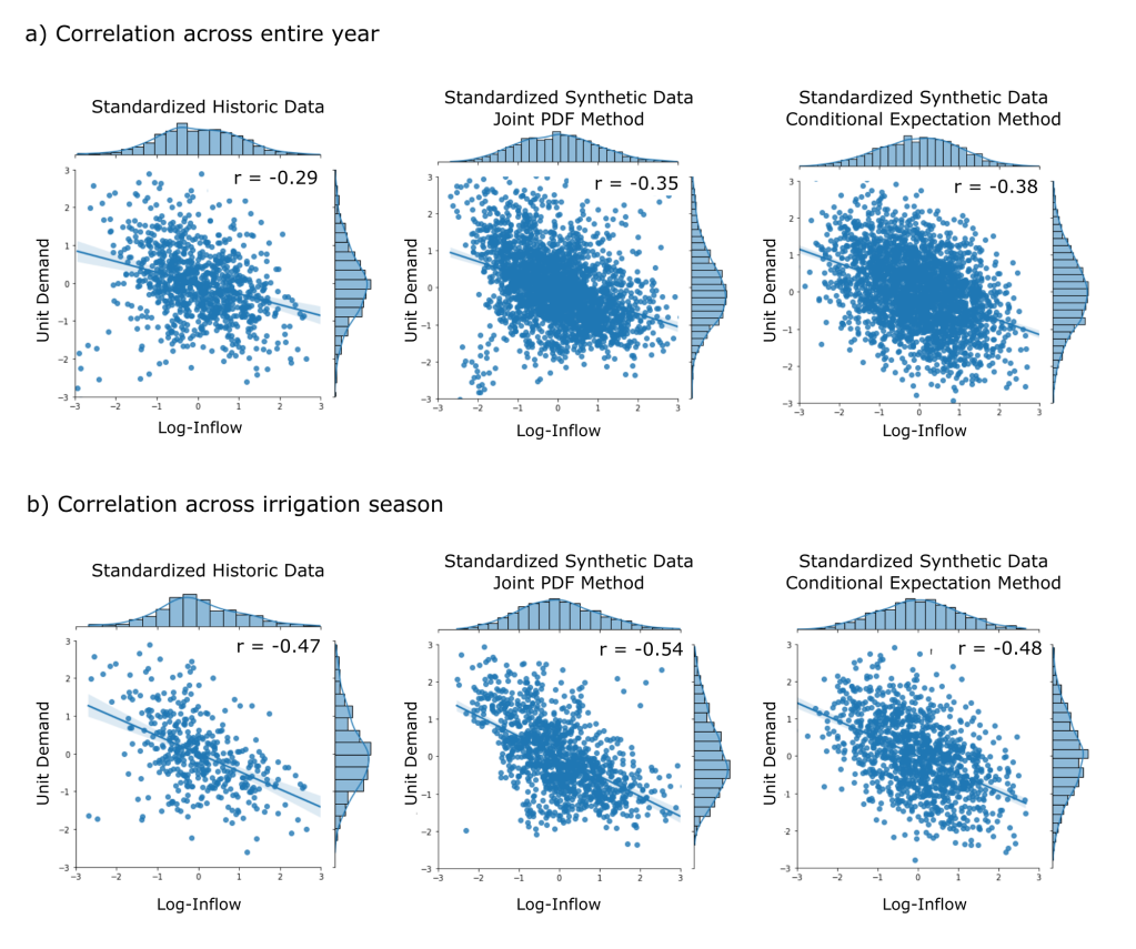
is the Pearson correlation coefficient of the weekly standardized historic inflow and demand data. Since the data is standardized, ( E[d] = 0 and \sigma_z = \sigma_d = 1) the above form of the equation simplifies to:

E[d|Z_{s_i}] = \rho (Z_{s_i})

Where d is standard synthetic demand and Z_{s_i} is the standard synthetic streamflow for the i^{th} week. The variance of the standard demand conditional upon the standard streamflow is then:

Var(d|Z_{s_i}) = \sigma_d^2(1 - \rho^2) = (1 - \rho^2)

The weekly standard demand, d_{s_i}, is then randomly sampled from a normal distribution centered around the conditional expectation with standard deviation equal to the square root of the conditional variance.

d_{s_i} \approx N(E[d|Z_{s_i}], Var(d|Z_{s_i})^{1/2})

As in the previous method, this method is performed according to whether the week is within the irrigation season or not. The correlation values used in the calculation of expected value and variance are calculated for both irrigated and non-irrigated seasons and applied respective of the week.

As in the first method, the standard synthetic demand is converted to a unit demand, and seasonality is reintroduced, using the weekly means and standard deviations of the historic demand:

D_{s_{i,j}} = d_{s_{i,j}} \sigma_{D_j} + \mu_{D_j}

Results

Historic Correlation Patterns

It is worthwhile to first consider the correlation pattern between stream inflow and demand in the historic record.

Figure 1: Correlation patterns between inflow and demand across weeks, for the historic record.

The correlation patterns between inflow and demand found in this analysis support the initial hypothesis that inflow and demand are correlated with one another. More specifically, there is a strong negative correlation between inflow and demand week to week (along the diagonal in the above figure). Contextually, this makes sense; low reservoir inflow correspond to generally dryer climatic conditions. When considering that agriculture accounts for a substantial contribution to demand in the region, it is understandable that demand will be high during dry periods, when are farmers require more reservoir supply to irrigate their crops. During wet periods, they depend less upon the reservoir supply.

Interestingly, there appears to be some type of lag-correlation, between variables across different weeks (dark coloring on the off-diagonals in the matrix). For example, there exists strong negative correlation between the inflow during week 15 with the demands in weeks 15, 16, 17 and 18. This may be indicative of persistence in climatic conditions which influence demand for several subsequent weeks.

Synthetic Streamflow Results

Figure 2: Comparison of the range of flow duration curves for the historic record (hist. = 81), and the synthetic streamflow data (nsyn = 50) generated using the mFGN method.

Consideration of the above flow duration curves reveal that the synthetic streamflow generated through the mFGN method exceedance probabilities are in close alignment with the historic record. While it should not be assumed that future hydrologic conditions will follow historic trends (Milly et al., 2008), the focus of this analysis is the replication of historic patterns. This result confirms previous studies by Mandelbrot and Wallis (1968) that the FGN method is capable of capturing flood and drought patterns from the historic record.

Synthetic Demand Results

Figure 3: Comparison of the ranges in unit demands in the historic record  (hist = 18) and the synthetic demand record (nsyn = 50) generated using both the joint PMF sampling method and the conditional expectation method.

The above figure shows a comparison of the ranges in unit demand data between historic and synthetic data sets. Like the synthetic streamflow data, these figures reveal that both demand generation techniques are producing timeseries that align closely with historic patterns. The joint probability sampling method does appear to produce consistently higher unit demands than the historic record, but this discrepancy is not significant enough to disregard the method, and may be corrected with some tweaking of the PDF-sampling scheme.

Synthetic Correlation Patterns

Now that we know both synthetic inflow and demand data resemble historic ranges, it is important to consider how correlation is replicated in those variables.

Figure 4: Correlation patterns between inflow and demand across weeks for both synthetic data generated using both the joint probability and conditional expectation methods.

Take a second to compare the historic correlation patterns in Figure 1 with the correlation in the synthetic data shown in Figure 4. The methods are working!

As in the historic data, the synthetic data contain strong negative correlations between inflow and demand week-to-week (along the diagonal).

Visualizing the joint distributions of the standardized data provides more insight into the correlation of the data. The Pearson correlation coefficients for each aggregated data set are shown in the upper right of each scatter plot, and in the table below.

Figure 5: Joint distributions for historic standardized inflow and demand using the full set of annual weekly observations (a) and irrigation-season data (b). Pearson correlation coefficients are included in the upper right of each plot.
Data TypeAnnual
Pearson Correlation
Irrigation Season
Pearson Correlation
Historic-0.29-0.47
Synthetic: Joint PDF Method-0.35-0.54
Synthetic: Conditional Expectation Method-0.38-0.48
Table 1: Pearson correlation coefficients for the historic data and the synthetic data sets, for the entire annual period and the irrigation seasons.

One concern with this result is that the correlation is actually too strong in the synthetic data. For both methods, the Pearson Correlation coefficient is greater in the synthetic data than it is in the historic data.

This may be due to the fact that correlation is highly variable throughout the year in the historic record, but the methods used here only separate the year into two seasons – non-irrigation and irrigation seasons. Aggregated across these seasons, the historic correlations are negative. However, there exist weeks (e.g., during the winter months) when weekly correlations are 0 or even positive. Imposing the aggregated negative-correlation to every week during the generation process may be the cause of the overly-negative correlation in the synthetic timeseries.

It may be possible to produce synthetic data with better preservation of historic correlations by performing the same demand generation methods but with more than two seasons.

Conclusions

When generating synthetic timeseries, it is important to replicate the historic means and variances of the data, but also to capture the correlation that exist between variables. Interactions between exogenous variables can have critical implications for policy outcomes.

For example, when evaluating water resource policies, strong negative correlation between demand and inflow can constitute a compounding risk (Simpson et al., 2021), where the risk associated with low streamflow during a drought is then compounded by high demand at the same time.

Here, I’ve shared two different methods of producing correlated synthetic timeseries which do well in preserving historic correlation patterns. Additionally, I’ve tried to demonstrate different analyses and visualizations that can be used to verify this preservation. While demonstrated using inflow and demand data, the methods described in this post can be applied to a variety of different timeseries variables.

Lastly, I want to thank David Gold and David Gorelick for sharing their data and insight on this project. I also want to give a shout out to Professor Scott Steinschneider whose Multivariate Environmental Statistics class at Cornell motivated this work, and who fielded questions along the way.

Happy programming!

References

Gold, D. F., Reed, P. M., Gorelick, D. E., & Characklis, G. W. (2022). Power and Pathways: Exploring Robustness, Cooperative Stability, and Power Relationships in Regional Infrastructure Investment and Water Supply Management Portfolio Pathways. Earth’s Future10(2), e2021EF002472.

Kirsch, B. R., Characklis, G. W., & Zeff, H. B. (2013). Evaluating the impact of alternative hydro-climate scenarios on transfer agreements: Practical improvement for generating synthetic streamflows. Journal of Water Resources Planning and Management, 139(4), 396-406.

Lettenmaier, D. P., Leytham, K. M., Palmer, R. N., Lund, J. R., & Burges, S. J. (1987). Strategies for coping with drought: Part 2, Planning techniques and reliability assessment (No. EPRI-P-5201). Washington Univ., Seattle (USA). Dept. of Civil Engineering; Electric Power Research Inst., Palo Alto, CA (USA).

Mandelbrot, B. B., & Wallis, J. R. (1968). Noah, Joseph, and operational hydrology. Water resources research, 4(5), 909-918.

McLeod, A. I., & Hipel, K. W. (1978). Preservation of the rescaled adjusted range: 1. A reassessment of the Hurst Phenomenon. Water Resources Research14(3), 491-508.

Simpson, N. P., Mach, K. J., Constable, A., Hess, J., Hogarth, R., Howden, M., … & Trisos, C. H. (2021). A framework for complex climate change risk assessment. One Earth4(4), 489-501.

Zeff, H. B., Herman, J. D., Reed, P. M., & Characklis, G. W. (2016). Cooperative drought adaptation: Integrating infrastructure development, conservation, and water transfers into adaptive policy pathways. Water Resources Research, 52(9), 7327-7346.